- A logic gate is an physical device implementing a boolean function, it performs a logical operation on one (or) more binary inputs and produce a single binary output.
- These gates are implemented by using diodes (or) transistors acting as electronic switches, in practice these are implemented by using CMOS technology, FETs, MOSFETs.
- These are used in multiplexers, registers, ALU's, and computer memory.
- There are seven basic logic gates:
1.AND
2.OR
3.NAND
4.NOR
5.XOR
6.XNOR
7.NOT
1.AND GATE:


 3.NAND GATE:


 5.XOR GATE:


1.AND GATE:
- It is a basic logic gate that implements logical operations on (or) more binary inputs and produce a single binary output.
- It behaves according to the
- Truth table:

- Symbol:
- AND gate by using NOR gate

- AND gate by using NAND gate
2.OR GATE:
- OR gate is a basic logic gate that implements logical operations on one (or) more inputs and produce a single output.
- It behaves according to the
- Truth table:

- Symbol:

- OR gate by using NOR gate

- OR gate by using NAND gate

- It is a Universal logic gate that implements logical operations on (or) more binary inputs and produce a single binary output.
- By using this gate we can design any logic gate.
- It behaves according to the
- Truth table:

- Symbol:

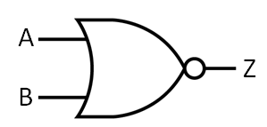
4.NOR GATE:
- It is a Universal logic gate that implements logical operations on (or) more binary inputs and produce a single binary output.
- By using this gate we can design any logic gate.
- It behaves according to the
- Truth table:
- Symbol:
- XOR gate is a basic logic gate that implements logical operations on one (or) more inputs and produce a single output.
- An XOR gate implements an exclusive or; that is, a true output results if one, and only one, of the inputs to the gate is true. If both inputs are false (0/LOW) or both are true, a false output results.
- It is a inequality function, i.e., the output is true if the inputs are not alike otherwise the output is false.
- It behaves according to the
- Truth table:

- Symbol:
- XOR by using NAND gate

- XOR by using NOR gate

6. XNOR GATE:
- XNOR gate is a basic logic gate that implements logical operations on one (or) more inputs and produce a single output.
- It's function is the logical complement of the exclusive OR (XOR) gate.
- XNOR gate is called an "equivalence gate".
- A high output (1) results if both of the inputs to the gate are the same. If one but not both inputs are high (1), a low output (0) results
- It behaves according to the
- Truth table:

- Symbol:

- XNOR by using NOR gate

7.NOT GATE:
- NOT gate is a logic gate which implements logical negation.
- It is also called as inverter gate
- It behaves according to the
- Truth table:

- Symbol:

- NOT by using NOR gate:

